Privacy statement: Your privacy is very important to Us. Our company promises not to disclose your personal information to any external company with out your explicit permission.
モデル: NSO4GU3AB
輸送方法: Ocean,Air,Express,Land
お支払い方法の種類: L/C,T/T,D/A
インコタームズ: FOB,EXW,CIF
4GB 1600MHz 240-PIN DDR3 UDIMM
改訂履歴
|
Revision No. |
History |
Draft Date |
Remark |
|
1.0 |
Initial Release |
Apr. 2022 |
|
![]()
情報テーブルの注文
|
Model |
Density |
Speed |
Organization |
Component Composition |
|
NS04GU3AB |
4GB |
1600MHz |
512Mx64bit |
DDR3 256Mx8 *16 |
説明
Hengstar Unbuffered DDR3 SDRAM DIMM(バッファーされていない二重データレート同期DRAMデュアルインラインメモリモジュール)は、DDR3 SDRAMデバイスを使用する低電力、高速操作メモリモジュールです。 NS04GU3ABは、16の256M X 8ビットFBGAコンポーネントに基づいて、512M X 64ビット2ランク4GB DDR3-1600 CL11 1.5V SDRAM Unbuffered DIMM製品です。 SPDは、1.5Vで11-11-11のJEDEC標準レイテンシDDR3-1600タイミングにプログラムされています。各240ピンディムは、金の接触指を使用します。 SDRAMのバッファードディムは、PCやワークステーションなどのシステムにインストールされた場合、メインメモリとして使用することを目的としています。
特徴
パワー供給:VDD = 1.5V(1.425V〜1.575V)
VDDQ= 1.5V(1.425V〜1.575V)
1600MB/秒/ピンの800MHz FCK
8独立した内部銀行
プログラム可能なCASレイテンシ:11、10、9、8、7、6
プログラム可能な添加剤のレイテンシ:0、CL -2、またはCL -1クロック
8ビット前フェッチ
バーストの長さ:8(制限なしでインターリーブ、開始アドレス「000」のみのシーケンシャル)、4で4でシームレスな読み取りまたは書き込みを許可しない[A12またはMRSを使用してその場で]
方向微分データストロボ
内部(自己)キャリブレーション。 ZQピンを介した内部自己キャリブレーション(RZQ:240オーム±1%)
ODTピンを使用して終了します
TCase85°C未満で低いリフレッシュ期間7.8U、85°Cで3.9US <TCase <95°C
同期リセット
調整可能なデータ出力ドライブ強度
一気にトポロジ
PCB:高さ1.18インチ(30mm)
ROHS準拠とハロゲンフリー
重要なタイミングパラメーター
|
MT/s |
tRCD(ns) |
tRP(ns) |
tRC(ns) |
CL-tRCD-tRP |
|
DDR3-1600 |
13.125 |
13.125 |
48.125 |
2011/11/11 |
アドレステーブル
|
Configuration |
Refresh count |
Row address |
Device bank address |
Device configuration |
Column Address |
Module rank address |
|
4GB |
8K |
32K A[14:0] |
8 BA[2:0] |
2Gb (256 Meg x 8) |
1K A[9:0] |
2 S#[1:0] |
ピンの説明
|
Symbol |
Type |
Description |
|
Ax |
Input |
Address inputs: Provide the row address for ACTIVE commands, and the column |
|
BAx |
Input |
Bank address inputs: Define the device bank to which an ACTIVE, READ, WRITE, or |
|
CKx, |
Input |
Clock: Differential clock inputs. All control, command, and address input signals are |
|
CKEx |
Input |
Clock enable: Enables (registered HIGH) and disables (registered LOW) internal circuitry |
|
DMx |
Input |
Data mask (x8 devices only): DM is an input mask signal for write data. Input data is |
|
ODTx |
Input |
On-die termination: Enables (registered HIGH) and disables (registered LOW) |
|
Par_In |
Input |
Parity input: Parity bit for Ax, RAS#, CAS#, and WE#. |
|
RAS#, |
Input |
Command inputs: RAS#, CAS#, and WE# (along with S#) define the command being |
|
RESET# |
Input |
Reset: RESET# is an active LOW asychronous input that is connected to each DRAM and |
|
Sx# |
Input |
Chip select: Enables (registered LOW) and disables (registered HIGH) the command |
|
SAx |
Input |
Serial address inputs: Used to configure the temperature sensor/SPD EEPROM address |
|
SCL |
Input |
Serial |
|
CBx |
I/O |
Check bits: Used for system error detection and correction. |
|
DQx |
I/O |
Data input/output: Bidirectional data bus. |
|
DQSx, |
I/O |
Data strobe: Differential data strobes. Output with read data; edge-aligned with read data; |
|
SDA |
I/O |
Serial |
|
TDQSx, |
Output |
Redundant data strobe (x8 devices only): TDQS is enabled/disabled via the LOAD |
|
Err_Out# |
Output (open |
Parity error output: Parity error found on the command and address bus. |
|
EVENT# |
Output (open |
Temperature event: The EVENT# pin is asserted by the temperature sensor when critical |
|
VDD |
Supply |
Power supply: 1.35V (1.283–1.45V) backward-compatible to 1.5V (1.425–1.575V). The |
|
VDDSPD |
Supply |
Temperature sensor/SPD EEPROM power supply: 3.0–3.6V. |
|
VREFCA |
Supply |
Reference voltage: Control, command, and address VDD/2. |
|
VREFDQ |
Supply |
Reference voltage: DQ, DM VDD/2. |
|
VSS |
Supply |
Ground. |
|
VTT |
Supply |
Termination voltage: Used for control, command, and address VDD/2. |
|
NC |
– |
No connect: These pins are not connected on the module. |
|
NF |
– |
No function: These pins are connected within the module, but provide no functionality. |
注:以下のピン説明表は、すべてのDDR3モジュールのすべての可能なピンの包括的なリストです。 5月にリストされているすべてのピン このモジュールではサポートされていません。このモジュールに固有の情報については、PIN割り当てを参照してください。
機能ブロック図
4GB、512MX64モジュール(X8の2rank)


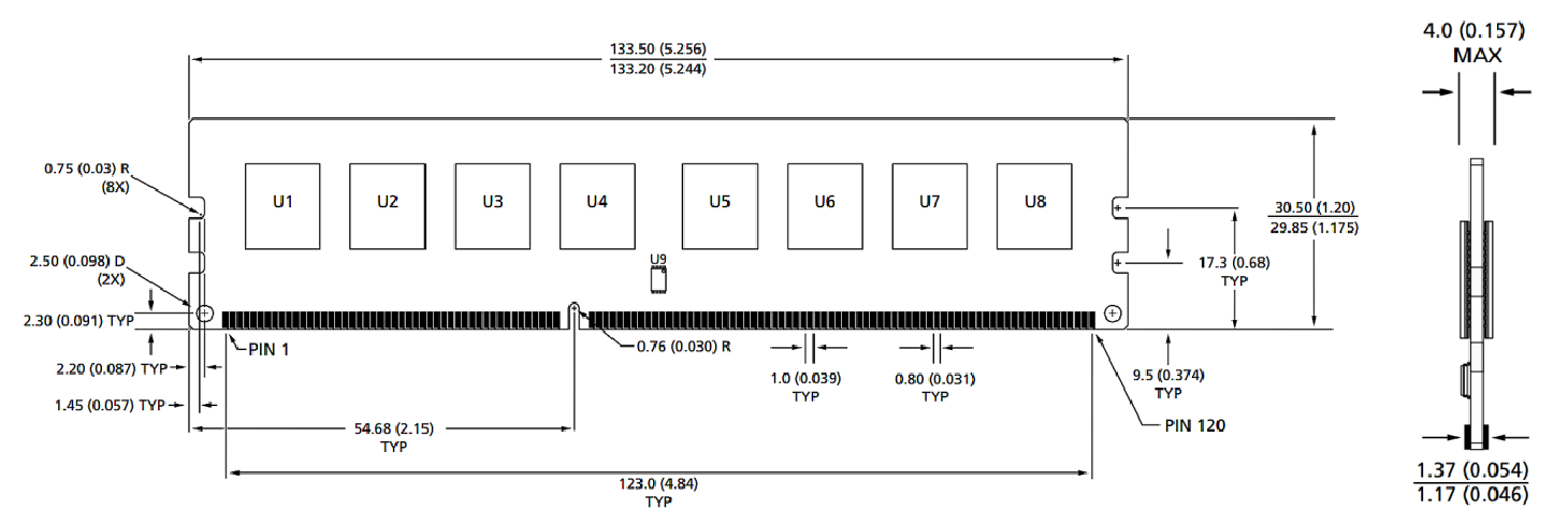
モジュールの寸法
正面図

正面図

ノート:
1.すべての寸法はミリメートル(インチ)です。記載されている場合は、最大/minまたは典型的な(typ)。
2.すべての寸法の耐性±0.15mm特に指定がない限り。
3.寸法図は参照用です。
製品グループ : 産業用スマートモジュールアクセサリー


Privacy statement: Your privacy is very important to Us. Our company promises not to disclose your personal information to any external company with out your explicit permission.

Fill in more information so that we can get in touch with you faster
Privacy statement: Your privacy is very important to Us. Our company promises not to disclose your personal information to any external company with out your explicit permission.